| Quick Search: Hit CONTROL-F to search this page directly with your browser! |
| Welcome To The Sphere Research Canadian Test Equipment Site ! Tektronix Spare Parts, Equipment and Service Information | ||||
 New info added: November 12, 2020 Click REFRESH on your browser if pages seem unchanged Everything from Quotes and SciFi to Ethics and Business. | Please Note: All Prices are in US$ |
Sphere Research Corporation 3394 Sunnyside Rd. West Kelowna, BC, Canada V1Z 2V4 Phone: +1 (250) 769-1834 A great source for test equipment, repairs, calibrations, useful metrology information, and of course, SLIDE RULES! JUST SCROLL DOWN TO SEE EVERYTHING | ||


Tektronix Web-based Support of all kinds
|
|
| W140.COM |
|
 |
|
 Some fascinating items, including an inexpensive NEW design for the always missing or broken SG504 leveling head, Tek 7T plug in tricks and more. Worth a visit! If you have ever been tempted to bid on a 1Ghz Tek SG504 generator, but didn't becuase the critical leveling head was missing, this site will solve your problems! |
|
May 25, 2004 Well, as it turns out, such a manual actually exists, although clearly not many people have ever seen it!. It is quite exhaustive, with flowcharts and some useful schematic diagrams. It was printed in 1989, and is called: Just click on the title to download the 94 page (3.7Mb PDF file) book. It is clearly a scanned original someone sent to me a while ago, and I have just lost track of its origin. Whoever you were, many thanks on behalf of everybody working on Tek equipment, and to Tek for allowing the material to now be copied. |
|
|
| |
| Tektronix 7000 Series
Another very nice Tektronix 7K illustrated index by Mark Kahrs, There is another great model reference site |

A clever way to fix CRT-based TDS disply problems!
| Got a bad display in your Tek TDS524A or similar magnetic CRT based scope? have a look here! A great step-by-step plan from Steve Noll to switch to a color LCD! Very elegant $70 solution. | 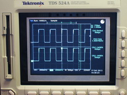 CLICK to visit! CLICK to visit! |
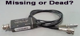
How to make a NEW Battery for your THS720 (or related) Scope!
| Got a dead battery, or need a new charger, here's detailed info on how to deal with these problems, and roll your own battery pack from scratch, you just need to still have your orignal battery! Click on the picture to the right to download the illustrated article. | Bring it back to Life!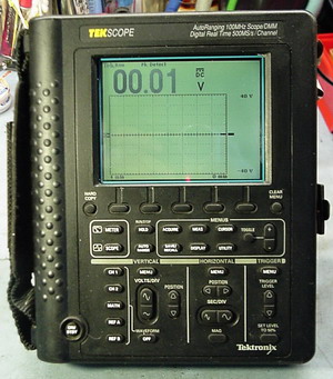 CLICK to download! |
SERVICE TOPIC: Tek Hybrids and Failures in 2400 series oscilloscopes
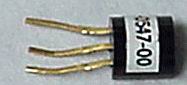
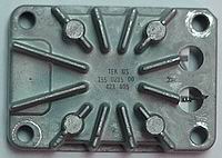 OVERVIEW: Tek 155 Series Hybrids OVERVIEW: Tek 155 Series HybridsThese parts are all in-house designs, NOT outside vendor parts, no substitutes exist except for other 155 or 165 series parts in some cases. They are removable (except the horizontal output hybrid, which is soldered in) by removing the 4 corner nuts, and pulling the heatsinked hybrid away from the board socket. Blocked ventilation causes premature failures of these parts due to poor air circulation and elevated temperatures. Later production of these parts shifted to Maxim when Tektronix sold the chip foundry to them, those parts are marked Maxtek, early ones tend to be a problem while they learned how to make the parts, later ones work pretty well. There is very limited stock of the 155 parts worldwide, EMAIL SUSAN if you need something, she will tell you the current stock and availability status. We have managed to work some deals with other international service centers to pool parts and provide one stop support via our facility. |
|
Date: May 13, 2004 From: Denis Cobley Tek hybrid failures: By MODEL NUMBER: All the hybrids do fail occasionally and I have noted the following most common failures below: By HYBRID TYPE: |
The Tek 155-0241-02 Re-Bake Program
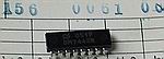
| Fixing 155-0241-02 Horizontal Driver ICs: This part has been an ongoing source of trouble in all 24xx series models, and is the most requested 155 spare part. Unfortunately, they are simply no longer available, so we have a different method to address this problem. We can provide this service for users in North America, or others who want to ship to us (but freight cost may be higher). Batches are done roughly once a quarter, depending on the quantity of available repair candidates. The process essentially attempts reattachment of the main die to the heatsink substrate, and is done at a semiconductor manufacturer's facility in Japan. Results to date have been good on many chips (100's) and the success rate of suitable candidates is approx. 70%. Any parts for re-work MUST be professionally de-soldered with FULL CLEAN LEADS. If badly removed or heat damaged further, there is no point in attempting repair, or in sending the part to us. This re-work is done in batches, and there must be a certain critical number of parts in Japan before work can start. Individual parts can be added to the batch in progress, but until at least 20 parts are collected, no work will be done. Batches are run roughly every quarter, whether parts from North America are ready or not, if late, they have to wait for the next processing cycle. What parts are suitable candidates? Those with thermal failures, which work briefly at power up, then shut down, or stop sweeping, some limited left/right position control must still be present. They may have reduced scan, big timing errors on the 1ns and 2 ns ranges, or exhibit thermal latch up. Parts with localized individualized pin failures of some sort or another or have catastrophic output failure are NOT fixable by this method. We cannot guarantee success, and approximately 5% of the fixed chips will re-fail within a year, due to fundamental design issues. When you pay to have your chip processed, and it is a suitable candidate, the odds favor success, but reality indicates that it may not work, or may fail again later. This is the limit of what is physically possible, so be sure you understand it going in. We have had excellent results with the repaired chips, as have many other customers. Send all your parts to Sphere Research Corporation, 3394 Sunnyside Rd., West Kelowna, BC, V1Z 2V4 CANADA. Airmail is fine, use a low declared value ($10), as the parts are BROKEN. Payment is required with the parts (can be US$ check, Visa/MC), and is US$70 per chip, and US$21 for return airmail expresspost shipping (US$91 total), regardless of how many parts are sent. Whether your parts work or not after processing, they will be returned to you. CONTACT US FIRST, by phone (250) 769-1834, or email. We will advise if enough parts can be grouped to do a batch, and if you are in time to join that batch. We will mark every part received, and generally your exact chip is the one returned to you, but the processor in Japan may simply return the right number of good working parts to us. If you wish to add your own marks, avoid damaging the part, or using anything that will be removed by solvent or other cleaners. If we feel the part is simply unsuitable for repair (mechanically damaged, etc.), we will return it to you using your US$21 shipping charge. We will try and post into the Tek user's group at least 2 weeks before we are assembling a batch for processing, but parts should be sent as soon as you have them ready, to avoid any delays. There is never a benefit in waiting to ship them. |
E-mail us about this program |
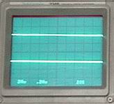
SERVICE TOPIC: Bizarre CRT Traces
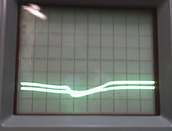 OVERVIEW: The CRT image has a strange center or side twist that gets worse as you move to one area (usually up or down), or is bad in all areas. OVERVIEW: The CRT image has a strange center or side twist that gets worse as you move to one area (usually up or down), or is bad in all areas.This effect occurs at all sweep speeds, and is the classic appearace of a broken CRT, where the internal glass supports have been broken though rough shipping (typically dropped) and the deflection plates are now distorted. There is only one fix, CRT replacement, and possibly filing a shipping insurance claim for damage in transit. |
SERVICE TOPIC: Tek CRT Replacement in the 2235
 OVERVIEW: The CRT for the 2235 scope is not common, and can be a serious service problem if it fails. The original CRT (154-0861-00) can be substituted by another, more easily obtained Tek tube under some conditions. Details are below. |
|
Date:
From: Ben Clark Tektronix 2235 CRT Replacement The mounting holes for these should already be drilled in the pcb (under the power supply cover) and they should show on the silk screen print so adding them is easy. Values are R879 510K 5% 0.25w, C879 Ceramic 0.1uF 200v, CR879 is 400v 750mA and has a Tek part number of 152-0413-00, shown as manufacturer's part number UTR307, but I have successfully used UF4007, or even the slower 1N4004 in this position. If the components are missing then most likely the wire between the circuit board and pin 12 of the CRT socket is also missing. Also a note on the 2235 CRT from Ben - the 154-0861-00 or -10 are used as a common CRT in the following models 2213A,2215A,2220,2221(A), 2230,2235,2236(A),2224 2232 so are often more common than 465 tubes (although experience in North America is usually the other way around, with the 465 tube being the common one due to decades of use). They are also normally much sharper than the 465/B CRT so I only like to swap them backwards. They also work in the 2213/2215 but you need to modify the PDA lead to suit the small spade terminal on the HV Multiplier. Added note: This also means you can probably work a substitution backwards in all the models above if no alternative tube can be found. |
SERVICE TOPIC: No plug-in lights on the 7603 Mainframe
 OVERVIEW: The Tek 7000 series plugs-ins with lighted pushbuttons do not light in the 7603 because there IS NO LIGHTING POWER sent to the plug in connections. For reasons that remain a mystery to us all, but presumably because the intended plug-ins (7A18, 7A26, 7B53A, etc.) simply did not require it, this connection is missing. In addition, the most common sweep plug-in used with the 7603, the 7B53A, looks like it has lighted pushbuttons, BUT IT DOES NOT. Net result? It is possible to route 5V lamp power to the plug-in slots, but it requires modifications to the frame, and will not light the 7B53A, no matter what you do. |
|
Date: August 27, 2004 From: Rolynn PRECHTL, K7DFW There is a very simple modification that can supply power to the plug-ins, as detailed below, but this IS NOT the method used by Tek in their mod kit. Here is the easy fix from Rolynn: I've done multiple units the cheap and dirty way. No additional regulator, no pulling the LVPS to find a place to add extra components and the best part, no cost. Look for P90 and P10 on the rear edge of the Main Interface circuit board (left side when viewed from the front). Connect P10-1 (gnd) to P90-7 or 8 (gnd). Connect P10-2 (+5V) to P90-4 (+5V). Two wires and you're done. I have experienced no problems with the extra current demand from the +5V regulated supply. K7DFW Here is the alternate (Tek factory mod) method from Stan Griffiths: The 040-0686-01 mod kit for 7600 series plugin lamps uses an LM309K (presumably a 7805 would also work) between +8 volts in the mainframe and +5 delivered to the plugin compartments for lamp power. Derating of the range of acceptable line voltages and operating temperature of the scope are required if the total plugin lamp current exceeds 1.5 amps. You just add up the lamp current requirements of each plugin to see if it exceeds 1.5 amps to know if you have to derate line voltage or temperature specs. The total kit instructions are on 7 pages of microfiche and installation instructions and a parts list are included along with a derating chart. I can provide hard copies of the instructions for 50 cents per page plus $1 for postage(total = $4.50). Stan |
SERVICE TOPIC: 465M, Mis-Operation & Shipping Problems
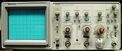
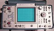 OVERVIEW: Often, the problem with a complex scope is mis-operation or the result of recent shipping. Here's some useful info to keep you out of trouble with that freshly arrived, multi-mode triggered scope. Some models like the 465M pictured to the left have recurring problems, so it helps to know about them in advance. |
|
|
Date:
From: Walter Shipping problems -This sounds obvious, but people forget that the rear voltage changeover switch can be set to different voltages, and sometimes it can be accidentally changed during packing or unpacking. This is especially important if buying a scope from North America (110V) for use elsewhere, as the line voltage is almost certain to be wrong in a dangerous way. Often a fuse change is also required before use at local 220V or 230V power. - Adjust the TRACE ROTATION pot, usually by or under the CRT on most portables, sometimes on the back (5000 series) or internal (7603, etc.) -This is often caused by a deflection plate wire pulling loose from the neck of the CRT, common on the 2200 series (very tight wire connection), but can occur on virtually all 400 series portables, and sometimes on the large 7000 series frames if the connections were loose. Not uncommon after rough shipping. Just remove the cover, and with all power OFF, replace the wire(s). -The 465M modular design is great (Vertical, CRT, Motherboard and Horizontal), and much easier to work on than the 465 or 465B, BUT it is easily destroyed just by leaving a few screws out. It is very common for this model to have been put back together with missing screws, and often missing support plates or top covers when sold surplus, or on ebay. The result is severe stress applied to the very small bottom mating connectors of the modules during shipping. This often breaks the end off the small edge connector, and then mis-aligns the pins, sometimes shorting every single pin together. If powered up in this way, the scope can be severely damaged, so ALWAYS open and visually inspect any newly arrived 465M for that problem before applying power. Replace any missing top mounting screws, plates, etc., and replace any damaged connectors before operation. Operating problems -The single most common operating problem is to accidentally move this switch (usually to GND) when changing vertical settings or connecting an input cable. The result is NO input signal displayed! Well, just put it to AC or DC coupling as required, and all will be well. Can't see the trace? PRESS BEAM FIND, it should appear, as it defeats many control settings. You may discover you have the trace positioned off screen, or have no sweep running. -This is the next big pitfall, and usually results in NO trace displayed. Tek scopes have very complex triggering, and it's easy to pick a control setting that does not trigger the sweep. To begin, use INTernal triggering, AUTO triggering, DC coupling, MAIN sweep and adjust the trigger level for a stable display and a TRIGgered light. You can rove from there. How to Take the Scope Apart! | |
SERVICE TOPIC: Troubleshooting 465 Sweep Problems
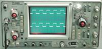 OVERVIEW: The Tek 465 has many interdependent functions, so knowing where to start with a service problem can sometimes be puzzling. Here is a very good sequential technique from Denis to lead you clearly to the solution. This info applies to many Tek scopes of this era, so check to see if it will help your other models as well. |
|
Date: May 21, 2004 From: Denis Cobley Tektronix 465 - no horizontal time base on both channels |
SERVICE TOPIC: TDS500 Series Capacitor Failures
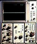
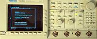 OVERVIEW: The Tek TDS500 series like the TDS540, used first generation surface mount technology with some tempermental parts. Early surface mount electrolytics were very poor quality, basically regular electrolytic cans with a bottom spacer, and they leaked after being IR reflow soldered, as the heat was simply too high to maintain the can seal. Here's the whole story, and how to fix it. OVERVIEW: The Tek TDS500 series like the TDS540, used first generation surface mount technology with some tempermental parts. Early surface mount electrolytics were very poor quality, basically regular electrolytic cans with a bottom spacer, and they leaked after being IR reflow soldered, as the heat was simply too high to maintain the can seal. Here's the whole story, and how to fix it. |
|
Date: May 17, 2004 From: Denis Cobley What happens: |
SERVICE TOPIC: CRT Problems and Cross-References
 OVERVIEW: The CRT is the heart of any analog scope, and there can be many different issues that create a visible problem on the CRT. Before you change the tube, read over these service suggestions. A model and part cross reference is also provided for some older tube types. |
|
|
Date:
From: Walter Tektronix CRT Issues Assuming you have correct CRT gun bias (look in the manual, and don't skip this adjustment!), and have looked at the horizontal and vertical drive signals, and they are UNDISTORTED, then: Odd waveform distortion (humps, curves, sudden angles) that is in the same physical place on the CRT (regardless of control settings) especially of very unusual shape, is generally caused by: 1. Magnetic Interference: this can be from accidentally magnetized parts within the CRT, adjacent hardware or an external source. Move the scope, if the interference is unchanged, degauss the tube and chassis with a standard TV degaussing coil (or any home made one excited by AC, very easy to make). If this improves matters, keep looking for the exact offending part, and degauss again, or remove the hardware that is magnetized. You can usually cure this problem, but it is time consuming. Severe magnetic distortion can be caused by a single magnetized screw in the wrong place. Don't sit a scope on top of a speaker cabinet or by speakers, or near anything with a magnetron in it, the results can be serious. MANY types of microwave test gear have strong magnets internally so check the position of these items first. Fans are also notorious for their strong external magnetic field, as are other magnetically deflected displays like computer monitors, TVs and CCTV displays. 2. Mechanical distortion within the tube: if the above technique doesn't work, the tube or the scope has probably been dropped, and the shock has broken or bent an internal electrode or support. If the tube exhibits the identical distortion outside the chassis, with the shield removed, it is damaged, and has to be replaced. Other CRT issues: 3. If the display is crooked relative to the graticule lines (goes at an angle), this is almost always the trace rotation adjustment, which may not be easy to find or readily accessible in some models. Generally, it is DC bias applied to a coil around the CRT neck, you may be able to find the control by following the coil wires back to the PC board. In many Tek models, it is at the front by the CRT itself, in the 5000 scope series, it is a pot on the rear panel. It is VERY common for this to be out of adjustment after shipping. Calibration is not affected by this adjustment. 4. If the display is turned up or down at the corners, or has an angled appearance, it is probably the geometry adjustment, and this can be complex to set, you must use the manual and follow the CRT alignment carefully. Calibration is affected. Some scopes have supplemental X or Y axis alignment as well, generally via coils. 5. If strange trace effects occur at the face of the tube when touched, it probably indicates high static build up on the display filter, or tube face. Clean the parts, then wipe everything down with a standard anti-static wipe, the effect will disappear. Plastic can be very highly charged when rubbed with a synthetic cloth for cleaning. Use a damp cotton cloth or anti-static wipe to avoid this effect. | |
Tek number cross reference for older CRT's courtesy of: |
-Tek 536- T536P1/T56P1 - 154-0140-00 T536P2/T56P2 - 154-0133-00 T536P7/T56P7 - 154-0135-00 T536P11/T56P11 - 154-0136-00 T536P16/T56P16 - 154-0169-00 -Tek 551- T551P1/T57P1 - 154-0186-00 T551P2/T57P2 - 154-0160-00 T551P7/T57P7 - 154-0189-00 T551P11/T57P11 - 154-0143-00 -Tek 531, 535, RM31, RM35- 5BGP1/T51P1A - 154-0080-00 5BGP2/T51P2A - 154-0081-00 5BGP7/T51P7A - 154-0082-00 5BGP11/T51P11A - 154-0083-00 5BGP16/T51P16A - 154-0092-00 5BGP24/T51P24A - 154-0124-00 -Tek 525, 532, RM32, 570, 575- 5CAP1/T52P1 - 154-0093-00 5CAP2/T52P2 - 154-0097-00 5CAP7/T52P7 - 154-0102-00 5CAP11/T52P11 - 154-0103-00 5CAP16/T52P16 - 154-0162-00 -Tek 541, 545, RM41, RM45- 5BHP1/T54P1 - 154-0106-00 5BHP2/T54P2 - 154-0098-00 5BHP7/T54P7 - 154-0104-00 5BHP11/T54P11 - 154-0099-00 5BHP16/T54P16 - 154-0118-00 5BHP24/T54P24 - 154-0152-00 And here's some more, where x denotes the phosphor. The scope type can then be used to get the 154 number from Stan's site: -Tek 316, RM16, RS16- T316Px/T32Px -Tek 503, 504- T503Px -Tek 507- T507Px/T53Px -Tek 519- T519A - P11 phosphor only -Tek 526- T526Px - Tek531A, RM31A, 533, RM33, 535A, RM35A- T533Px/T64Px -Tek 541A, RM41A, 543, RM43, 545A, RM45A- T543Px/T65Px -Tek 555- T551Px/T59Px -Tek 581, 585- T581Px 551 listed above was later replaced by T5511Px 502 listed above was later replaced by T5021Px |
| IMPORTANT ! Graphical logos and trademarks are the property of their respective owners, including Tektronix, Fluke, RCA, TI, GE, General Radio and Hewlett Packard, and are used here merely to unambiguously identify the products. Sphere Research IS NOT a factory authorized distributor for any of the product lines indicated. |
| ||
 | You are visitor number
Site Design & contents copyright 1997, 1998 1999, 2000, 2001, 2002, 2003, 2004, 2005, 2007, 2009, 2012, 2014 by Walter Shawlee 2 & the ad hoc Godzilla Graphics Group. All rights reserved.
|